GPS – RTC to DCF77 Module for Clock with DCF in.
Variant 1 with cable connection.

Assembly instructions, here
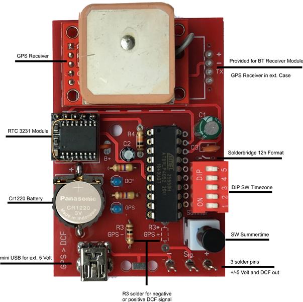
- GPC Module received UTC (Coordinated Universal Time ) Time, Date and Weekday
- 5 Dip Switches adjusting local Time ( SW 5 is for + or – time selection )
- Solder bridge for 12h format selection.
- Switch to select start and end of summertime.
The MCU unit get the UTC time and modified Time and Date for the local area.
Local time and date are programmed each minute by the RTC 3231 module, which
has a battery to support its internal memory.
The RTC output controls the MCU unit, which converts the signal to real DCF
Protocol. Positive or negative output is possible.
First Usage
- Set all DIP switches to OFF position including in the SW Summertime
- Install the CR1220 battery
- Connect the +/- 5 Volt supplies from your clock, external USB Power supply or Power Bank
-Solder the Sig. point to your clock.
Note: most clocks have – signal input, + signal is possible when R3 is soldered to * position.
The best location for the GPS receiver is on the window ledge.
In my office in the Ground floor it works too.
The GPS module has a dedicated rechargeable battery, allowing the time and date
Data to be stored in the internal RTC circuit when the GPS signal is out of range.
Please allow 30 to 60 minutes for battery charging and time to acquire the GPS signal.
The red LED from the GPS module is on and the blue DCF LED on the main board flashes.
When the GPS signal from 3 satellite is received the red LED flashes.
The blue GPS LED is on for 2 seconds each minute. ( i.e.-on at second 00 to 02 ), which
means the time and date has been written to RTC 3231 module.
After 2 – 3 minutes your clock will display UTC time.
Adjusting Time for your local area.
Look at the world map and search for the United Kingdom. There is UTC time.
If you look to the west site, it is UTC+ time. Look for the east it is UPS – time
Check your local time to see what time is it and compare with the following table.
DIP SW settings:
|
Time |
SW 1 |
SW 2 |
SW 3 |
SW 4 |
SW 5 |
Time |
SW 1 |
SW 2 |
SW 3 |
SW 4 |
SW 5 |
|
|
|
UTC |
off |
off |
off |
off |
on |
UTC |
off |
off |
off |
off |
on |
|
|
|
UTC + 1h |
on |
off |
off |
off |
on |
UTC - 1h |
on |
off |
off |
off |
off |
|
|
|
UTC + 2h |
off |
on |
off |
off |
on |
UTC - 2h |
off |
off |
off |
off |
off |
|
|
|
UTC + 3h |
on |
on |
off |
off |
on |
UTC - 3h |
on |
on |
off |
off |
off |
|
|
|
UTC + 4h |
off |
off |
on |
off |
on |
UTC - 4h |
off |
off |
on |
off |
off |
|
|
|
UTC + 5h |
on |
off |
off |
off |
on |
UTC - 5h |
on |
off |
off |
off |
off |
|
|
|
UTC + 6h |
off |
off |
on |
off |
on |
UTC - 6h |
off |
off |
on |
off |
off |
|
|
|
UTC + 7h |
on |
on |
on |
off |
on |
UTC - 7h |
on |
on |
on |
off |
off |
|
|
|
UTC + 8h |
off |
off |
off |
on |
on |
UTC - 8h |
off |
off |
off |
on |
off |
|
|
|
UTC + 9h |
on |
off |
off |
on |
on |
UTC - 9h |
on |
off |
off |
on |
off |
|
|
|
UTC + 10h |
off |
off |
off |
on |
on |
UTC - 10h |
off |
off |
off |
on |
off |
|
|
|
UTC + 11h |
on |
on |
off |
on |
on |
UTC - 11h |
on |
on |
off |
on |
off |
|
|
|
UTC + 12h |
off |
off |
on |
on |
on |
UTC - 12h |
off |
off |
on |
on |
off |
|
Set the switches accordingly and after 2 – 3 minutes the time, date and weekday is displayed on your clock.
Notes.
The GPS reception can be restricted by bad weather, cloudy or fog so is it not necessary to receive GPS continuously, because the internal RTC unit from the GPS module will keep good track of the time.
There is also a precise RTC 3231 module on main PCB that controls the clock.
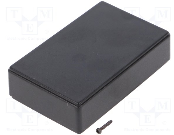
Enclosure: 90mm x 57mm x 24mm, ABS, black

The prize is 56,00€ + 7,80€ shipping. Upgrade IV-11 DCF melody, without DCF module, 34,00€
