DCF77 Module for IV-11 DCF, IV-11 melody and IV 6 - 3A clock.
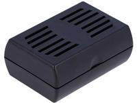
The kit consists of DCF receiver module with ferrite antenna, LED, resistor. Solder pins, PCB, flexible shielded connection cable with 3.5mm jack plug and cable straps. The PCB is installed in a black half shell housing 65mm x46mm x 26mm
Why the DCF receiver in an external housing and not on
the CPU board?
The DCF signal is sended by LW Radio transmitter near
Frankfurt. Receivers for LW have a ferrite antenna.The antenna must
be aligned to Frankfurt.
So It would be bad now to turn the whole clock. It is simpler
to align the small housing with the ferrite antenna.
It is possible to use a 3.5mm jack extension cable to place the
housing where reception is.
So it makes no sense to have a DCF receiver on Main
Board.
Signaling the LED on the DCF Board and VFD
Board.
- LED flash for 200ms and 800ms pause when initializing the DCF
signal. (The LED in the receiver flashes exactly)
- LED flash 500ms and 500ms pause when DCF is present. (The LED in
the receiver still flashes 200ms / 800ms, DCF77 clock)
- the seconds LEDs or VFD Dot did not light up if the DCF signal is
not present. (The clock runs with internal quarz)
- every 10 sec. displaying date for 2 sec. (The date is not
displayed if no DCF signal)
Here a small Videoclip.
The Video is from 29.01.2014
Der Bausatz, kpl. mit allen Bauteilen, Anschlußkabel und Schalengehäuse 18,00 € + Versandkosten
( Kombiversand mit mit den VFD Bausätzen )
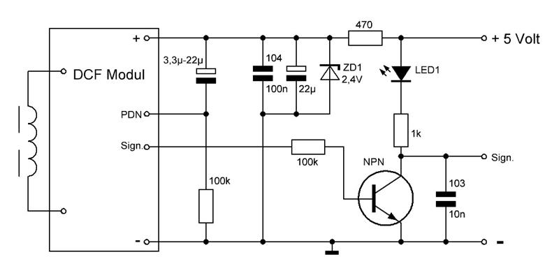
Hier die Schaltung.